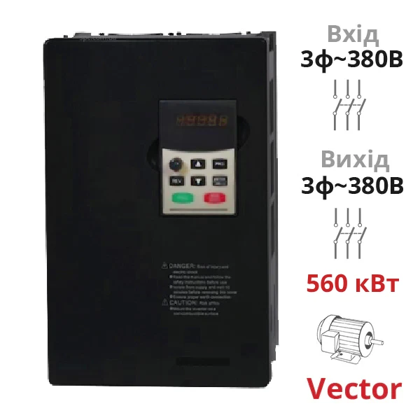
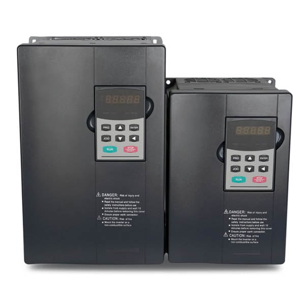
High-performance vector frequency inverters of the SPLC-NZ8400-560G/630P series are designed to control high-load three-phase electric motors 380V with a power of up to 560 kW, where overloads may occur, and high demands are placed on control quality. These frequency inverters have higher processor performance than the SPLC-AT20 series, allowing SPLC-NZ8000 to perform operations faster and thereby ensure sensorless vector control of rotational speed with an accuracy of ±0.5%. If necessary, the inverter can switch to simple scalar control mode U/f with lower accuracy and "Pump" mode for operating with more powerful motors but with less load (details below).
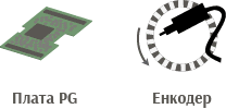
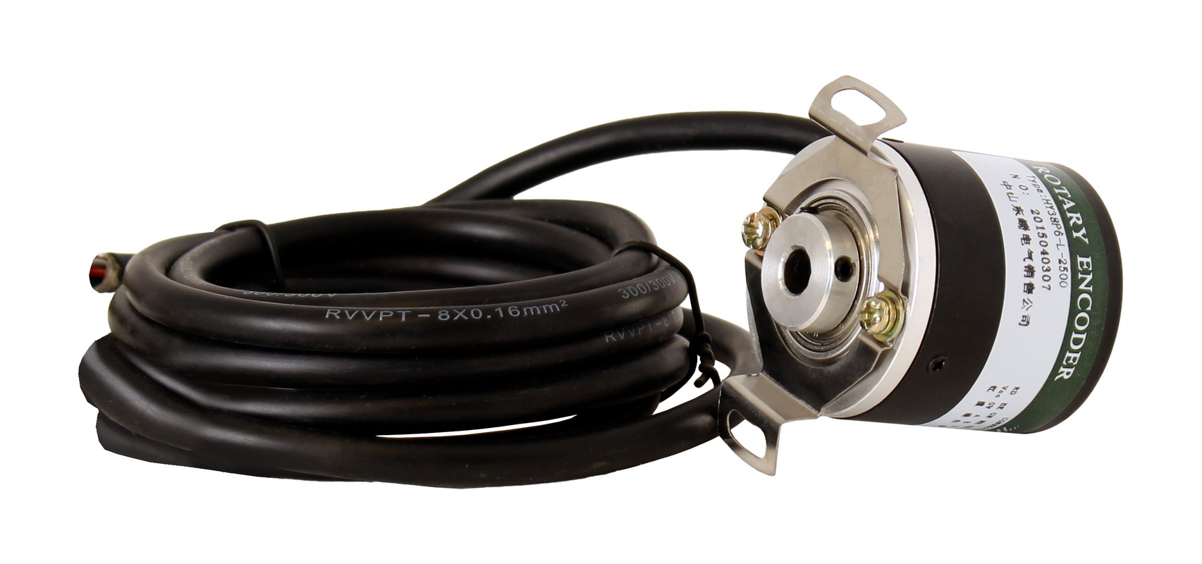
The SPLC-NZ8000 inverter can also be optionally equipped with a PG board (purchased separately). With it, a sensor-encoder can be connected to the inverter to monitor the motor’s rotational speed and rotor position. Closed-loop vector control provides enhanced responsiveness and rotational frequency control accuracy up to ±0.02%, allowing control of torque with an accuracy of ±5% and working not only with asynchronous but also synchronous motors.
Table — Main technical parameters of frequency inverters SPLC-NZ8400-560G/630P
| Input Voltage |
3ph 380 V
|
| Output Voltage |
3ph 380 V
|
| Output Power |
up to 560 kW (630 kW in "Pump" mode)
|
| Output Frequency Range |
from 0.1 to 3200.0 Hz (V/f) |
| Rated Input Current |
920 A (1050 A in "Pump" mode)
|
| Rated Output Current |
950 A (1100 A in "Pump" mode)
|
| Protection Level EN 60529 |
IP20 |
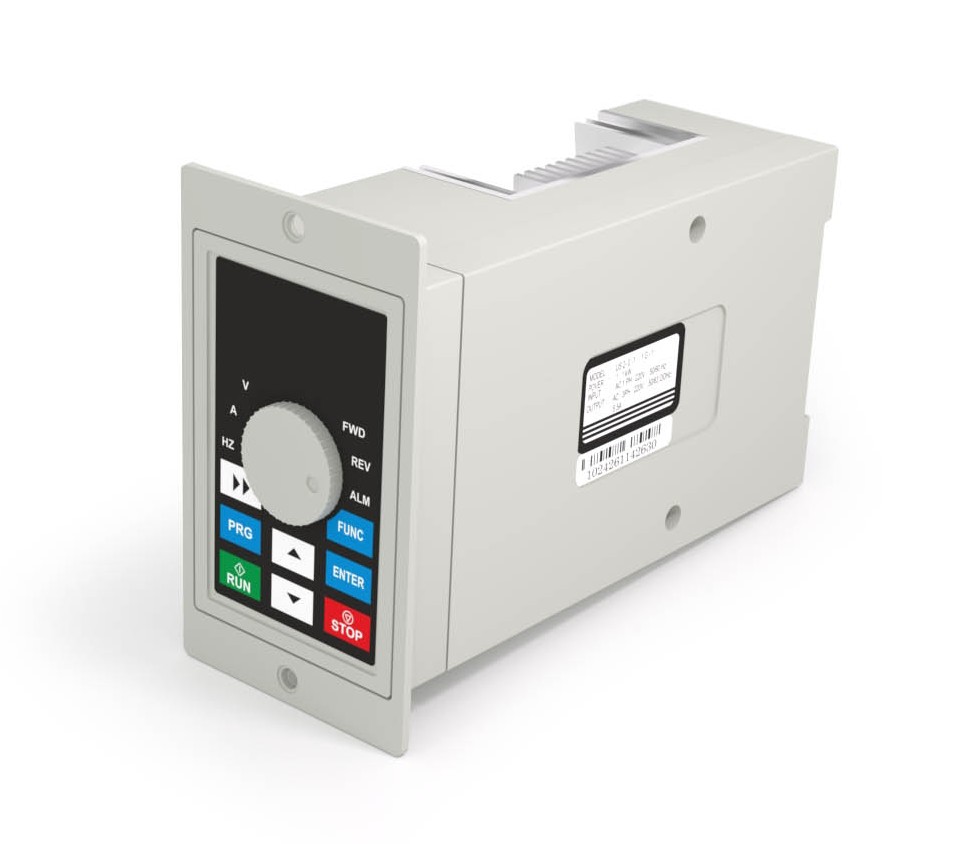
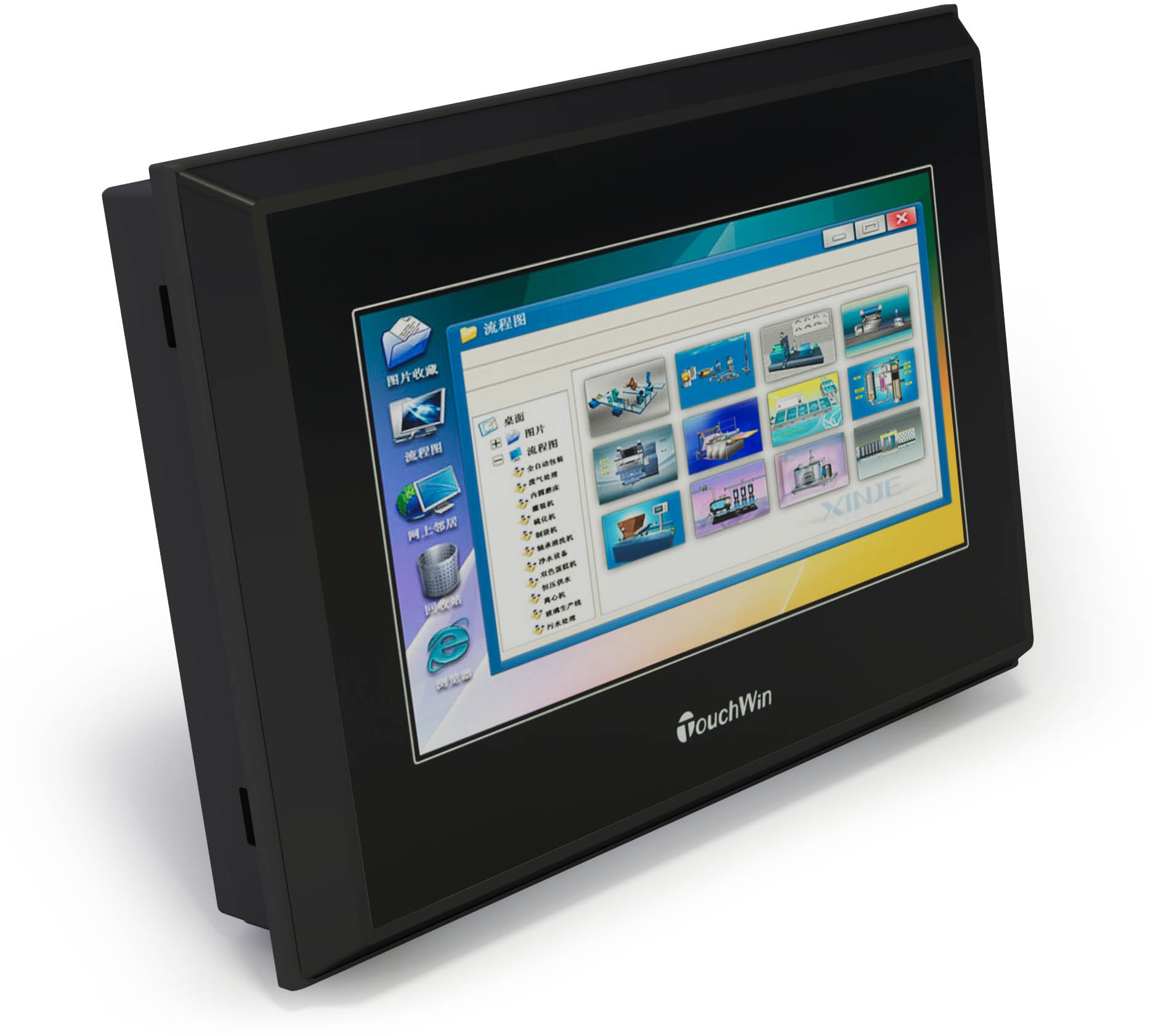
When installing the frequency inverter in a protection cabinet, its control panel (operator panel) can be detached and mounted on the front panel. A connecting cable needs to be purchased for this purpose.
Technical Specifications of the SPLC-NZ8000 Series
Standard Functions of the SPLC-NZ8000 Frequency Inverter
| Control Modes |
Sensorless vector control (SFVC)
Closed-loop vector control (CLVC, with PG)
Volt-frequency (V/F) control |
| Maximum Output Frequency |
Vector control: 0-320 Hz
V/F control: 0-3200 Hz
|
| Carrier Frequency |
1-16 kHz
Carrier frequency is automatically adjusted depending on the load characteristics. |
| Frequency Setting Resolution |
Digital setting: 0.01 Hz
Analog setting: maximum frequency × 0.025% |
| Starting Torque |
Type G: 0.5 Hz/150% (SFVC); 0 Hz/180% (CLVC, with PG)
Type: 0.5 Hz/100% |
| Speed Range |
1:100 (SFVC)
1:1000 (CLVC)
|
| Speed Accuracy |
±0.5% (SFVC), ±0.02% (CLVC, with PG)
|
| Torque Control Accuracy |
±5% (CLVC, with PG) |
| Overload Capability |
G type: 60 s at 150% of rated current, 3 s at 180% of rated current
P type: 60 s at 120% of rated current, 3 s at 150% of rated current |
| Torque Boost |
Auto boost
Manual boost 0.1%-30.0%
|
| V/F Curve |
Linear V/F curve
Multi-point V/F curve
Step V/F curve (1.2, 1.4, 1.6, 1.8, quadratic) |
| V/F Separation |
Two types: full separation, partial separation |
| Acceleration/Deceleration Mode |
Linear curve
S-curve
Four groups of acceleration/deceleration time range 0.0-6500.0 s
|
| DC Braking |
DC braking frequency: from 0.00 Hz to maximum frequency
Braking time: 0.0-100.0 s
Braking current selectivity: 0.0% -100.0%
|
| JOG Control |
JOG frequency range: 0.00-50.00 Hz
JOG acceleration/deceleration time: 0.0-6500.0 s
|
| Built-in Multi-stage Speeds |
Implementation of up to 16 speeds via simple PLC function or terminal state combination |
| Built-in PID |
Activating PID regulation in the closed-loop system |
| Auto Voltage Adjustment |
Can maintain a constant output voltage when the main voltage changes. |
| Overcurrent and Overvoltage Management |
Automatically limits current and voltage during operation to prevent frequent overcurrent or overvoltage trips. |
Enabling simple scalar control in SPLC-NZ8000 inverters makes it possible to choose the "General" or "Pump" load type in the menu.
-
General — general industrial mode for motors operating with approximately the same torque at different speeds (compressors, conveyors, lifts). In this mode, the frequency inverter can provide a starting torque of more than 150% for acceleration to overcome friction and inertia forces.
-
Pump — specialized mode for fans, pumps, and other electric motors operating with a torque that increases with rotational speed and where high starting torque is not required.
Thus, the frequency inverter SPLC-NZ8400-560G/630P is designed to control motors up to 560 kW, but when switching to scalar control and "Pump" mode, it can control a motor up to 630 kW. However, permissible overload is reduced: if in the regular "General" mode, load of no more than 150% for 60 s or 180% for 3 s is allowed, then in "Pump" mode with a more powerful motor, these figures are lowered — overloads of no more than 120% for 60 s or 150% for 3 s are permitted.
Individual Functions of SPLC-NZ8000
| Support for Various PG Boards |
Support for PG boards for rotating transformer, differential input, differential input UVW, resolver, and open collector input |
| Ride Through Power Drop |
Voltage drop is compensated by feedback load energy, allowing the drive to continue operating for a short time. |
| Rated Current Limitation |
Helps avoid frequency drive overcurrent faults. |
| High Performance |
Control of asynchronous and synchronous motors is implemented using high-performance vector current technology. |
| Time Management |
Time range: 0.0-6500.0 min |
| Communication Method |
Modbus (standard)
Profibus-DP (optional)
CANlink (optional)
CAN (optional) |
| Protection Modes |
Detection of motor short circuit upon start-up, protection from phase loss, overcurrent, overvoltage, undervoltage, overheating, and overload protections. |
Circuit Diagram of Frequency Inverter SPLC-NZ8400-5R5G/7R5P
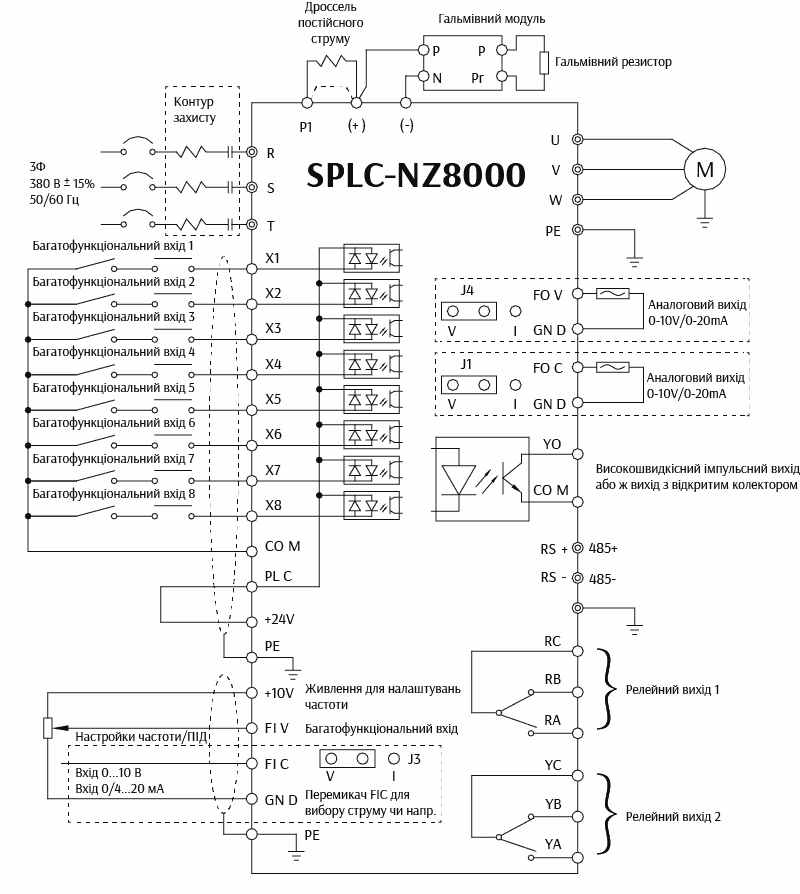
SPLC-NZ8000 includes multifunctional input-output control terminals, whose functions can be independently set in the settings — to define the preset frequency, issue the forward run command, stop, etc.:
- Inputs: 8 digital inputs (including one high-speed pulse), 2 analog inputs (one 0...10 V or 0...20 mA, the other only +10...-10 V);
- Outputs: 1 digital transistor output (high-speed), 2 relays 250 VAC 3 A or 30 VDC 1 A, 2 analog outputs (0...10 or 0...20 mA).
By default, the frequency inverter supports the most commonly used communication port RS-485 in enterprises across Ukraine, but upon request, these frequency inverters can be delivered with a board for Profibus or CAN, allowing easy integration of the equipment into any modern industrial network.








 On order