



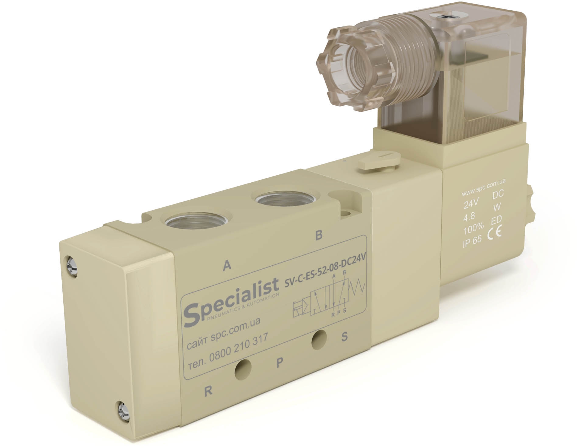


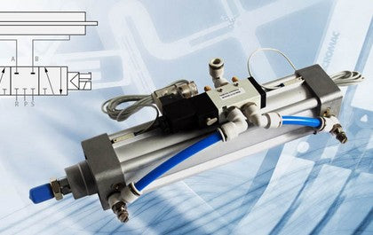
A pneumatic directional control valve is a control device used to switch compressed air flows. The valve switches by moving a spool inside its body. The movement of the spool changes the sequence of channel connections within the valve body and changes the direction of the airflow.
Pneumatic directional control valves available for purchase on our website.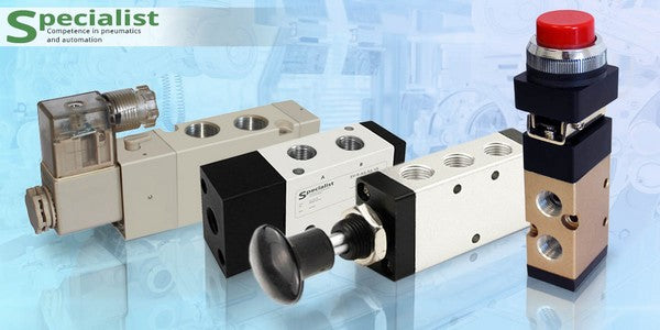
Pneumatic Directional Control Valves
Classification of Pneumatic Directional Control Valves
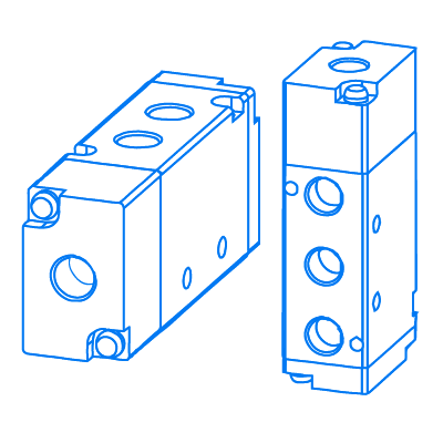
As an example, let's look at how a 5/2 pneumatic directional control valve works, such as the 4v210-08
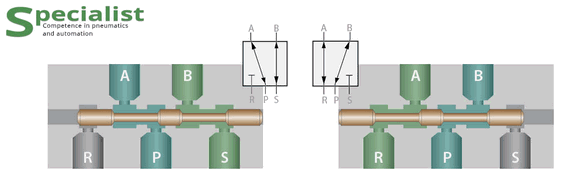
The total number of ports on the body of such a valve is 5. They are marked with numbers or letters and are called channels.
Channel 1 is used to connect compressed air to the valve and may also be marked with the letter "P". Channels 2 and 4 (or "A" and "B") are outlet ports and are used, for example, to connect the valve to a double-acting cylinder. Channels 3 and 5 (or "R" and "S") are used to exhaust air from the cylinder. Quick exhaust valves, silencers, and similar devices are often installed on the exhaust ports.
The operating principle of the valve is as follows:
- If we move the spool to the right side (image on the left), air will be supplied from inlet P to outlet A, while pressure from the second outlet B will be released through exhaust S.
- When the spool is moved to the left side (image on the right), air from channel P is directed to outlet B, while air from the first outlet A is exhausted through outlet R.
Thus, moving the spool creates two states of the valve, which are called positions. Directional control valves have at least two positions.
Main Characteristics of Directional Control Valves
Therefore, four main characteristics of a pneumatic directional control valve can be identified:
- Number of ports, indicating how many openings the valve has through which compressed air enters and exits. As a rule, all ports have cylindrical pipe threads from G1/8″ to G1″, allowing pipelines and silencers to be connected. All ports are marked with letters or numbers on the valve body.
- Number of positions reflects the number of possible inlet-outlet connection configurations depending on the spool position. Most commonly there are two or three. That is, depending on its design, the spool inside the pneumatic directional control valve can occupy two or three positions.
- Nominal flow rate usually indicates the volume of air that can pass through the pneumatic directional control valve when the inlet pressure is 6 bar and the outlet pressure is 5 bar. Flow capacity depends on the valve design, its dimensions, and the diameters of the connection ports. In the "Specialist" catalog, flow-versus-pressure graphs are provided separately for some valve series.
- Control type refers to the method used to move the spool. Valves are available with electric, electro-pneumatic, pneumatic, mechanical, and manual control.
Types of Pneumatic Directional Control Valves by Number of Ports and Positions
Methods of Indicating the Number of Ports and Positions
To indicate the type of pneumatic directional control valve, a designation consisting of two numbers separated by a slash is used. For example, "4/2 pneumatic directional control valve" indicates that the device has four ports and two positions. In pneumatic diagrams, a directional control valve is represented by a symbol in which the number of squares indicates the number of operating positions, while the ports are marked with letters or numbers.
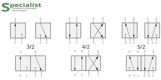
The most common valve types are 3/2, 4/2, 4/3, 5/2, and 5/3. We will examine them in more detail.
3/2 Directional Control Valves: Design, Features, and Applications
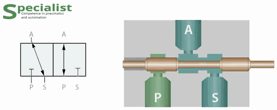
3/2 directional control valves are pneumatic valves that have three ports for connection to a pneumatic system and a spool that can occupy two fixed positions. Depending on the control type and valve design, they are available in three types:
- Normally open and normally closed pneumatic directional control valves contain a spring that returns the spool to its initial position as soon as the control signal is removed. Therefore, these valves are called monostable.
- 3/2NO — 3/2 normally open. In these pneumatic directional control valves, air from inlet 1 immediately flows to outlet 2 without requiring any control signal.
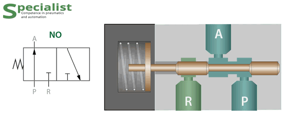
Diagram and design of a 3/2 normally open pneumatic directional control valve - 3/2NC — 3/2 normally closed. In these pneumatic directional control valves, air from inlet 1 does not immediately flow to outlet 2. Instead, outlet 2 is connected to exhaust 3. To supply air to outlet 2, a control signal must be applied to the valve.
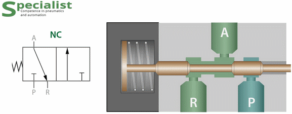
Diagram and design of a 3/2 normally open pneumatic directional control valve - If there is no spring in the design, the valve is bistable. This means the spool remains in the position to which it was last moved by a control signal. Such valves are designated 3/2 (without the NO or NC suffix).
Applications of 3/2 Directional Control Valves
3/2 pneumatic directional control valves are most commonly used:
- To control single-acting cylinders.
- To supply and release pressure to and from a reservoir.
- They can also be used in pneumatic logic circuits as NOT elements (3/2NC), YES elements (3/2NO), and memory elements (3/2).
Our website offers 3/2 pneumatic directional control valves.
4/2 and 4/3 Directional Control Valves: Design, Features, and Applications.
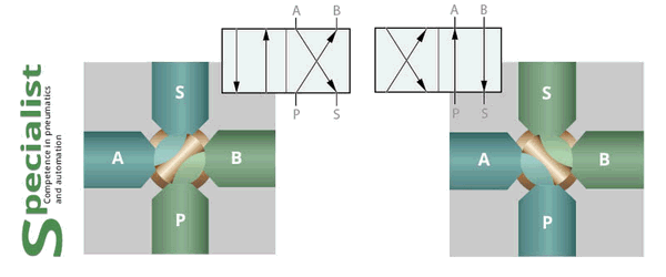
4/2 directional control valves have four ports for connection to a pneumatic system and a spool that can occupy two fixed positions.
Follow this link to find 4/2 pneumatic directional control valves available on our website.
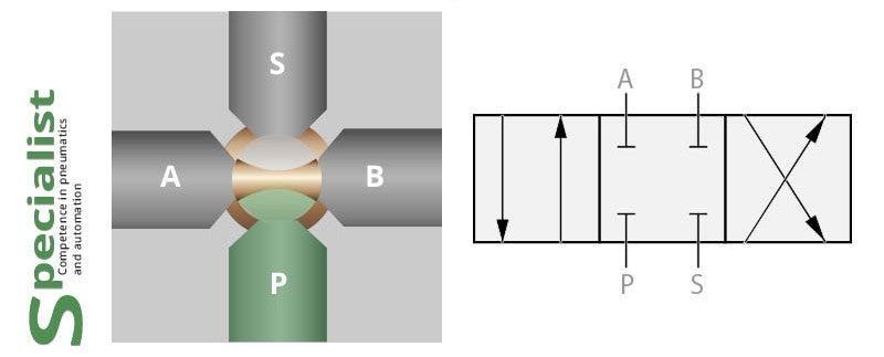
4/3 are compressed-air directional control valves that have four ports on the body for connection to a pneumatic system and a spool inside the body that can occupy three fixed positions. In the central position of such valves, all channels are blocked, meaning air is neither supplied nor exhausted. Such valves are called closed-center directional control valves and are designated as 4/3C.
This type of valve is extremely rare. Most often, these are plug valves with a flat spool and manual control. They are mainly installed on heavy-duty vehicles and in places where it is difficult to ensure proper air preparation in dirty and old industrial environments.
At this link, you can find 4/3C pneumatic directional control valves sold on our website.
5/2 Directional Control Valves: Design, Features, and Applications
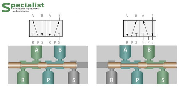
5/2 is a pneumatic directional control valve that has five ports on the body for connection to a pneumatic system and a spool inside the body that can occupy two fixed positions.
These are the most common pneumatic directional control valves and are most often used to control double-acting pneumatic cylinders.
At this link, you can find all 5/2 pneumatic directional control valves sold on our website.
Types of 5/2 Pneumatic Directional Control Valves
5/2 pneumatic directional control valves are divided into two types:
- Monostable — these valves have a spring in their design that returns the spool to its initial position after the control signal is removed. Bistable
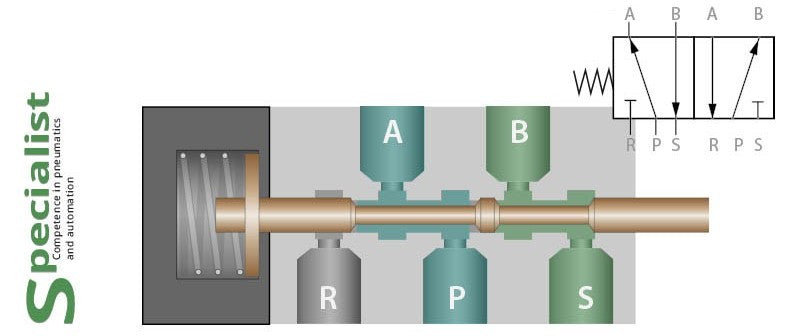
- Bistable — these valves do not have a spring in their design, therefore after the control signal is removed, the spool does not change its position and the direction of airflow remains unchanged.
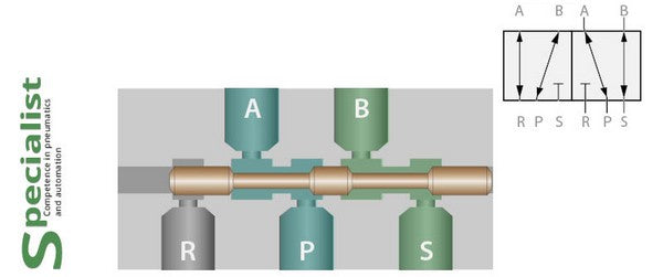
The main advantage of bistable valves is that the control signal can be applied briefly, after which the directional control valve will remain switched until the opposite control signal is applied.
5/3 Directional Control Valves: Design, Features, and Applications
5/3 directional control valves are similar to 5/2 valves but have an additional intermediate position. Depending on the type of this intermediate position, they are divided into three subtypes:
- 5/3 closed-center directional control valve
- 5/3 directional control valve with pressure supplied to both chambers
- 5/3 open-center directional control valve
At this link, you can find all 5/3 pneumatic directional control valves sold on our website.
5/3 Closed-Center Directional Control Valve
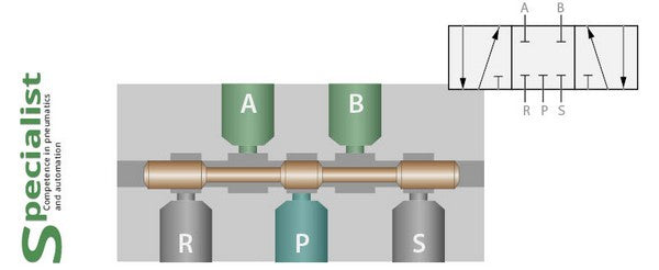
5/3 closed-center pneumatic directional control valves have five ports on the body for connection to a pneumatic system, and their spool can occupy three positions. In the central position, all channels are blocked, meaning air is neither supplied nor exhausted. Closed-center valves are designated as 5/3C.
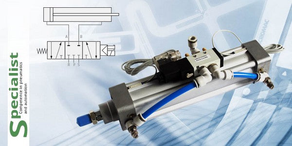
A 5/3C directional control valve can be used to stop a pneumatic cylinder in an intermediate position. However, when using these valves, it should be taken into account that they do not provide precise stopping of the cylinder piston.
Need help choosing?
If you need equipment for precise stopping of a pneumatic cylinder in intermediate positions, contact the company "Specialist". Our engineers develop pneumatic, electrical, and electronic control systems of any complexity for industrial automation processes.
Call free of charge within Ukraine
+38 0800 210 3175/3 directional control valve with pressure supplied to both chambers
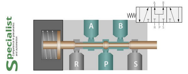
Compressed air directional control valves with pressure supplied to both outputs have five ports on the body for connection to the pneumatic system and a spool inside that can occupy three fixed positions. In the central position of such valves, compressed air is simultaneously supplied to both outputs 2 and 4 (A and B).
These valves are designated as 5/3P.
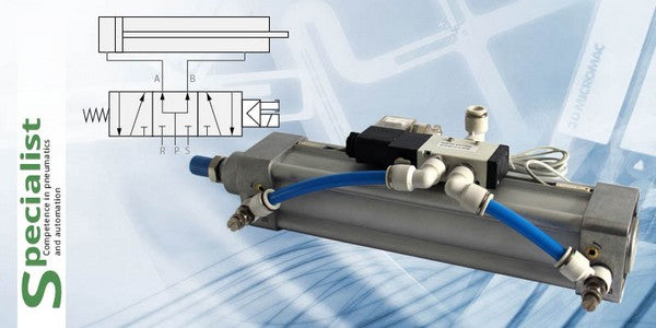
These valves are used to control pneumatic cylinders in cases where it is necessary to achieve two force levels on the cylinder rod — a main force and a reduced force without using additional pressure regulators.
If a pneumatic cylinder with a single rod extension is connected to such a valve, compressed air will be supplied to both chambers of the cylinder. In this case, if there are no external loads on the rod, it will extend with a small force. This is because the piston area on the cap-end side is larger than the area on the rod side, so the resulting force will be directed toward rod extension, although it will not be large.
The force directed toward extending the cylinder rod is equal to the rod diameter multiplied by the pressure supplied through the valve.
5/3 directional control valve with open center
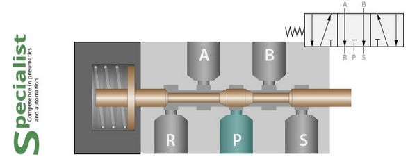
Pressure inlet port 1 is simultaneously connected to the two outlet ports 2 and 4. These valves are used to control pneumatic cylinders in applications where two force levels are required on the cylinder rod — a main force and a reduced force without additional pressure regulators. If a pneumatic cylinder is connected to such a valve, compressed air will be supplied to both chambers of the cylinder. In this case, the cylinder rod will reliably extend with a small force. This is because the area of the cap-end chamber is larger than the area of the rod-end chamber, and the resulting force will be directed toward rod extension, although it will not be large.
5/3E are compressed air directional control valves that have five ports on the body for connection to a pneumatic system and a spool inside that can occupy three fixed positions. In the central position of such valves, both outlet ports 2 and 4 are connected to exhaust ports 3 and 5.
Such valves are called 5/3E open-center pneumatic directional control valves.
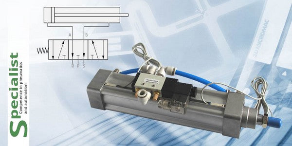
This type of valve is convenient for machines with manual adjustment, where cylinders need to be moved manually during equipment setup. When no control signals are applied to an open-center valve, both chambers of the pneumatic cylinder connected to it are vented to the atmosphere, allowing the cylinder to be moved easily by hand if there are no external mechanical influences.
This type of valve is convenient for machines with manual adjustment, where cylinders need to be moved manually during equipment setup. When no control signals are applied to an open-center valve, both chambers of the pneumatic cylinder connected to it are vented to the atmosphere, allowing the cylinder to be moved easily by hand if there are no mechanical obstacles.
Moving parts of equipment may be hazardous, so adjustments should only be performed by personnel with appropriate qualifications and knowledge. Before moving the rod, ensure that power is disconnected and that the corresponding controls are marked with “maintenance stop” signs.
Types of pneumatic directional valve control
Pneumatic directional control valves have four main control types: electro-pneumatic, pneumatic, mechanical, and manual.
Electro-pneumatic control
Electrical coils with voltages of 12, 24, or 48 volts DC and 24, 48, 110, or 220 volts AC are used to control such valves.
The term “electro-pneumatic” emphasizes the indirect method of electrical control. Its key feature is that the spool is moved by air pressure supplied to a pilot chamber through an additional built-in valve. In other words, when a signal is applied to the coil, it opens the pilot valve rather than the main valve, and the air pressure moves the spool.
This design allows the use of low-power coils, which improves energy efficiency. However, it also affects the minimum pressure the valve can switch. Since the air from the valve inlet is used to actuate the spool, the valve cannot switch pneumatic lines with pressures below 1.5 bar.
To overcome this limitation, directional control valves with external pilot air supply were developed. Such valves can switch air at pressures below 1.5 bar, provided that the pilot control ports receive a separate air supply above 1.5 bar.
We will consider the structure of both types of valves with single-sided and double-sided electro-pneumatic control. In the illustrations, pay attention to the small internal channel through which air is supplied to the electric pilot valve (the air supply line to the spool opened by the energized coil).
5/2 monostable pneumatic directional control valve with single-sided electro-pneumatic control
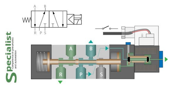
A five-port, two-position (5/2) monostable directional control valve with single-sided electro-pneumatic control has one solenoid coil, while a return spring is responsible for returning it to its stable position. This is the most commonly used type of pneumatic directional control valve.
If no electrical signal is applied, the spool remains in its stable position and air from inlet 1 is directed to outlet 4. If a control signal is applied to the coil, the pressure from inlet 1 switches to outlet 2, while outlet 4 is connected to the exhaust port. As soon as power to the coil is removed, the spool returns to its original position. This is why the valve is called monostable — when the signal is removed, it always returns to its default position.
Pneumatic directional control valves with this type of control are used to switch airflow at pressures from 1.5 to 10 bar. If it is necessary to switch pressures below 1.5 bar, valves with external pilot supply are used, which are described below.
Purchase 5/2 pneumatic directional control valves with electro-pneumatic control when the pressure in your system exceeds 1.5 bar and air should be directed to one outlet most of the time, while switching to the other outlet occurs only briefly.
5/2 bistable pneumatic directional control valve with double-sided electro-pneumatic control
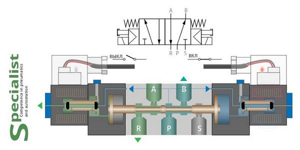
A five-port, two-position (5/2) bistable directional control valve with double-sided electro-pneumatic control has two solenoid coils.
A short electrical signal applied to one of the coils is enough to switch the valve to the corresponding position, where it remains until a control signal is applied to the opposite coil. The valve can remain indefinitely in either of its two positions, which is why it is called bistable.
Pneumatic directional control valves with this type of control are used to switch airflow at pressures from 1.5 to 10 bar. If pressures below 1.5 bar must be switched, valves with external pilot supply are used.
Pneumatic control
This type of control is used for 3/2 and 5/2 monostable valves, as well as 3/2, 5/2, and 5/3 bistable pneumatic directional control valves.
When pneumatic control is used, the valve can switch any pressure from zero up to the maximum allowable pressure for that type of valve.
On our website, you will find all of the above-mentioned pneumatic directional control valves with pneumatic control that we sell.
Manual and mechanical control
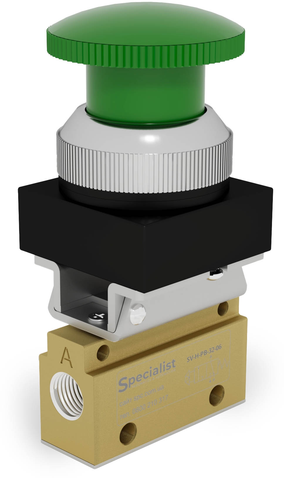
The following elements are used for manual and mechanical control: standard and emergency push buttons, joysticks, pedals, rollers, levers, and whisker actuators.
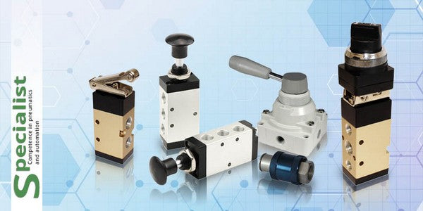
Manual and mechanical control valves are also available in two types: bistable and monostable.
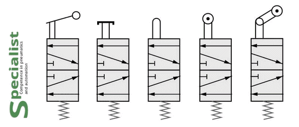
Monostable valves have a return spring that returns the spool to its initial position after the mechanical force acting on the valve is removed.
A small exception in this case is emergency push buttons. After pressing such a button, the valve remains locked in the switched position, and to return it to its original position, the button must be turned in the direction indicated by the arrow on the valve body.
Follow this link to find all pneumatic directional control valves with mechanical control sold on our website.
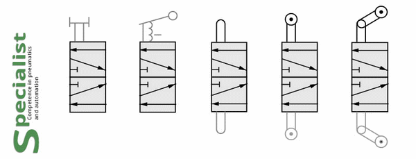
As for bistable valves, they have two fixed positions. The spool is held in these positions by the valve’s internal design.
Follow this link to find all bistable mechanical valves sold on our website.
5/3 valves can also have manual control. In the case of these valves, the control element has three fixed positions.
5/3 valves can also be available with only one central fixed position, to which the joystick always returns by means of built-in springs inside the valve.
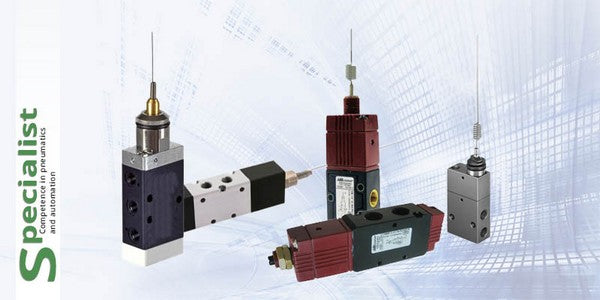
The most interesting mechanically controlled valve is the whisker-actuated valve.
This valve allows the force required for switching to be minimized. For example, this valve can easily be actuated by a bottle or a cardboard box moving along a conveyor.
Applications of pneumatic directional control valves
- Connecting valves to actuators
- Using pneumatic directional control valves to control pneumatic cylinders
- Using pneumatic directional control valves to control pneumatic vibrators and other devices
- Examples of pneumatic directional control valve applications in industry
Frequently Asked Questions About Pneumatic Directional Control Valves
What types of pneumatic directional control valves are there?
According to the number of ports/positions, pneumatic directional control valves are divided into:
- 3/2 pneumatic directional control valves
- 3/2NO normally open
- 3/2NC normally closed
- 3/2 bistable
- 4/2
- 4/3
- 5/2
- 5/3
According to the control type:
- direct electric control (rare)
- electro-pneumatic control
- pneumatic control
- manual control (buttons, levers, pedals, etc.)
- mechanical control (rollers)
What is a pneumatic directional control valve used for?
Pneumatic directional control valves are used for:
- controlling pneumatic mechanisms such as single-acting and double-acting pneumatic cylinders, pneumatic vibrators, and pneumatic actuators for shut-off valves
- switching air supply between different lines
- building pneumatic logic circuits based on directional control valves

