





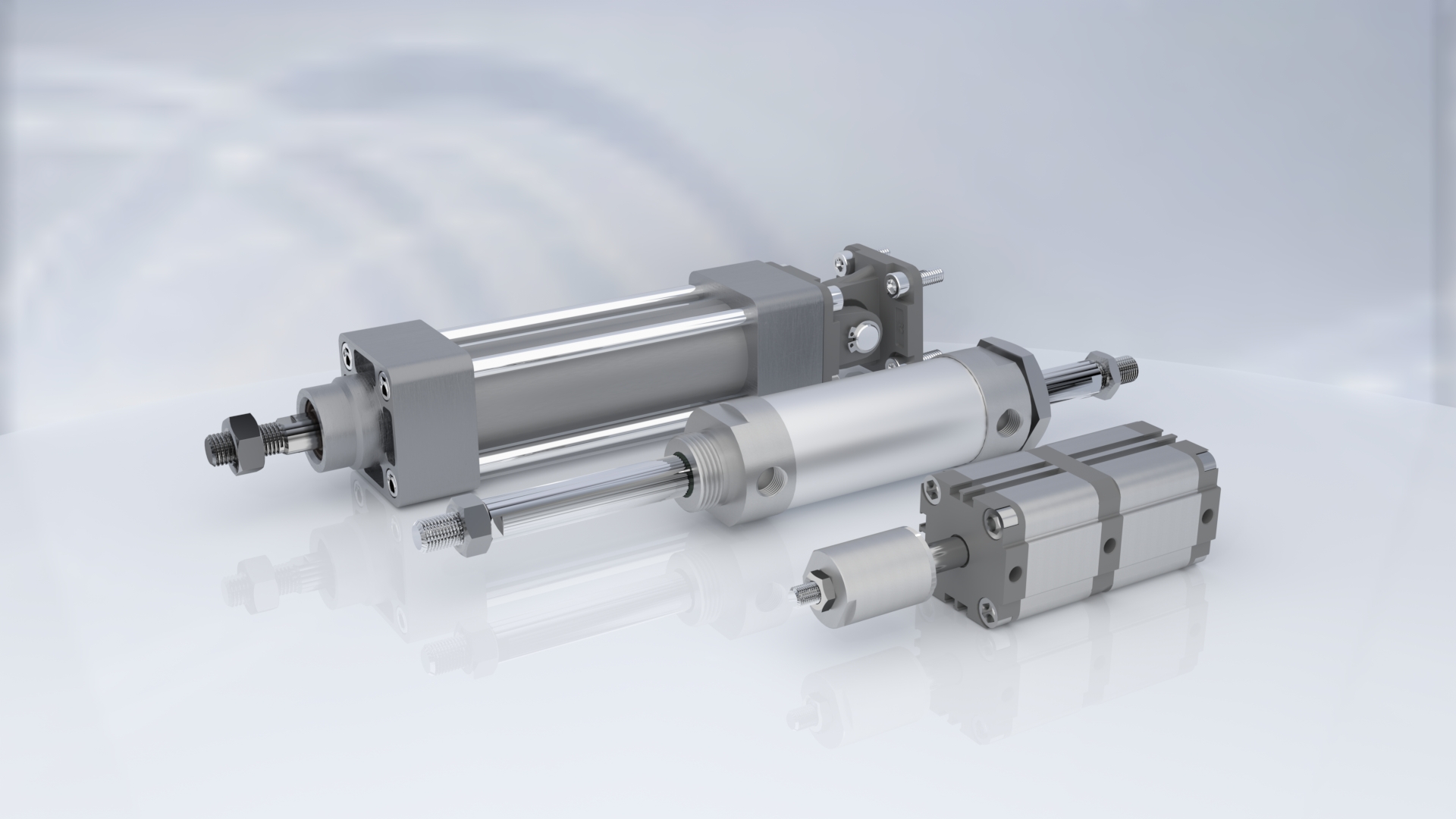
In this article, we will answer a number of common questions that will help you navigate the wide range of pneumatic cylinders and choose the right cylinder for your application.
- What types of pneumatic cylinders are there?
- What are pneumatic cylinders used for?
- How to calculate the diameter of a pneumatic cylinder?
- How to choose the right pneumatic cylinder?
- What is the difference between a hydraulic cylinder and a pneumatic cylinder?
- Does a pneumatic cylinder need lubrication?
- How to properly mount a pneumatic cylinder?
- How to increase the speed of a pneumatic cylinder?
What types of pneumatic cylinders are there?
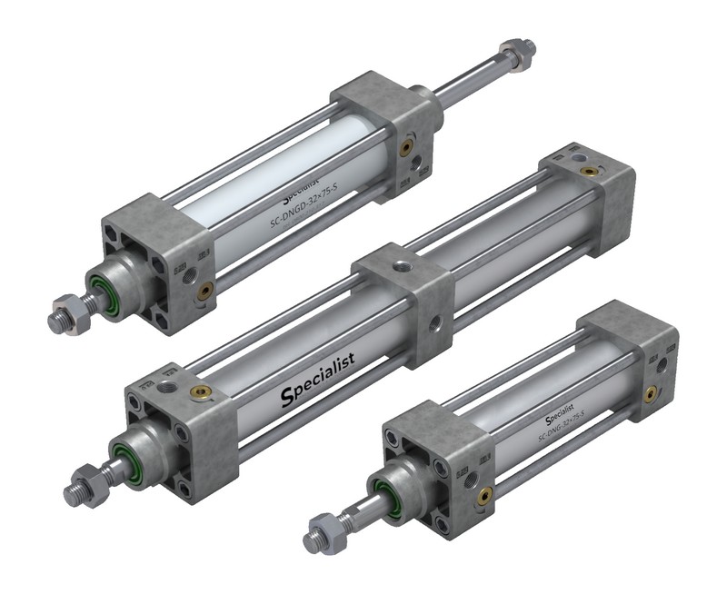
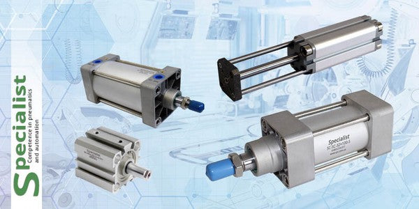
There are different types of pneumatic cylinders according to their design and manufacturing standard.
By Design
There are several types of pneumatic cylinders used in various applications. Here are some of the most common types:
- Single-acting cylinder: This is the simplest type of cylinder in which air pressure is applied in only one direction, while the piston returns by means of a spring or an external force.
- Double-acting cylinder: In such cylinders, the rod moves under the action of compressed air supplied to both sides of the piston.
- Piston cylinders: These are the most common type of pneumatic cylinders in which the piston moves inside the cylinder, converting air pressure into mechanical motion.
- Rodless cylinders: These cylinders do not have a rod. A carriage is mounted on the cylinder and moves along it, providing linear motion. It is connected to the piston through a magnetic or mechanical coupling.
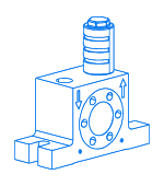
- Rotary cylinders: These are special cylinders that provide rotational movement. They can be used, for example, to rotate objects or valves.
In addition, there are many variations and combinations of these basic cylinder types, including specialized cylinders for specific applications. Our company develops custom cylinders and is ready to manufacture any analogue of your existing cylinder or develop one specifically for your project and application.
By Manufacturing Standard
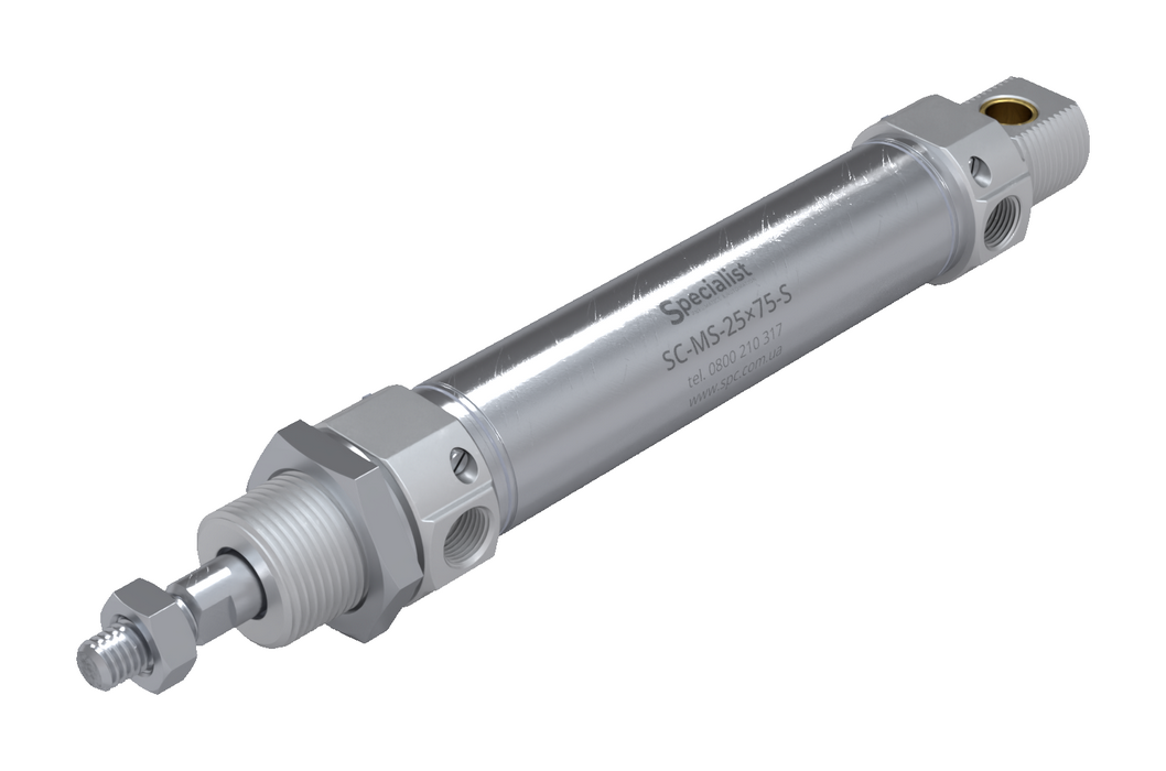
- ISO6432 describes a series of round pneumatic cylinders (SC-MS series) that feature a stainless-steel barrel and aluminum end caps. Variants of this series may be equipped with cushioning (SC-MS series) or operate without it (SC-MA series). These pneumatic cylinders are manufactured with piston diameters ranging from 8 to 32 mm. They are often used in applications where low force but high movement speed is required.
- ISO6431, also known as ISO 15552, is a group of cylinders that includes the SC-CPI, SC-DNG, and SC-DNI series. These series are among the most common and feature built-in adjustable cushioning. The cylinder covers and barrels are made of aluminum, while the rod can be chrome-plated or made of stainless steel according to customer preference. Manufactured with piston diameters ranging from 32–320 mm.
- ISO6430 is represented by the SC-SC cylinder series, which has a similar design to cylinders manufactured according to ISO6431, but differs in several key features. They have reduced dimensions, a smaller front bushing, and different mounting hole dimensions.
- ISO21287 describes compact pneumatic cylinders of the SC-JDA series. The covers and barrel are made of aluminum, while the rod can be chrome-plated or stainless steel. The barrel has a T-slot for installing piston position sensors. A magnet on the piston is installed upon customer request. Cylinders of this series do not have adjustable cushioning and instead use rubber bumpers on the piston.
What are pneumatic cylinders used for?
Pneumatic cylinders are used to convert compressed air into mechanical motion. They are widely used in various industries and manufacturing processes due to their simplicity, reliability, and relatively low cost. Here are some of the areas where pneumatic cylinders are most commonly used:
- Industrial manufacturing: Pneumatic cylinders are used for automation and mechanization of various industrial processes such as moving objects, pressing, extending, lifting, and lowering.
- Robotics: In robotics, pneumatic cylinders are used to create moving parts of robots such as arms, legs, or joints. They provide the linear or rotary motion required for performing robotic tasks.
- Transportation and logistics: Pneumatic cylinders are used in transportation systems to move conveyor belts, lifting platforms, doors, and other devices. They are also used in pneumatic conveying systems where material movement occurs under the action of compressed air. They help ensure smooth and efficient cargo handling.
- Automotive industry: In the automotive industry, pneumatic cylinders are used to control door locks, power windows, braking systems, clutches, and other mechanisms.
- Medical equipment: In some medical devices, such as dental chairs or operating tables, pneumatic cylinders are used to adjust position and movement.
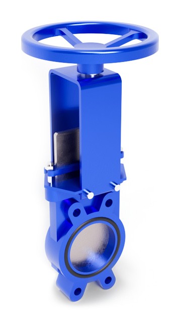
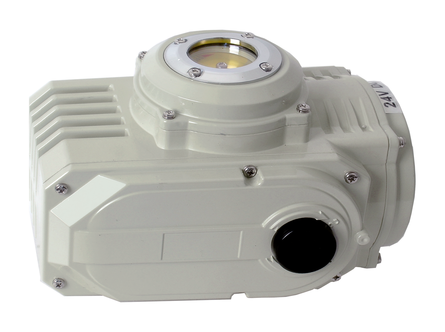
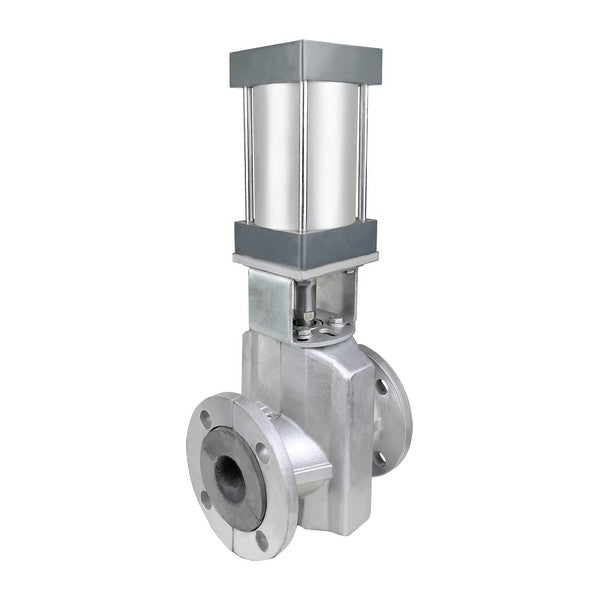
- Valve control: Pneumatic cylinders are used to control valves in water supply, heating, ventilation, and industrial systems. They allow opening, closing, or regulating the flow of liquids or gases. Single-acting actuators, where a spring allows the valve to close in only one direction, are often used in safety systems.
These are just a few examples of pneumatic cylinder applications. In general, they are widely used wherever simple and reliable motion control using compressed air is required.
How to calculate the diameter of a pneumatic cylinder?
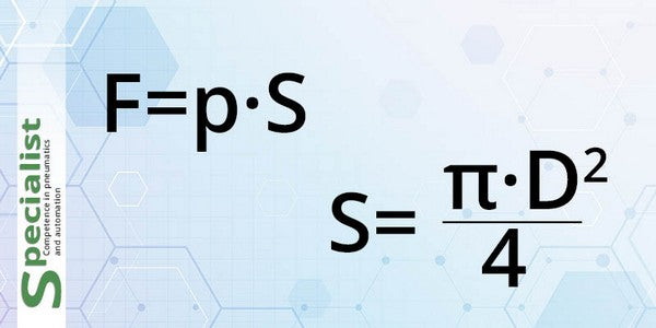
The calculation of a pneumatic cylinder diameter depends on several factors, including the required force, required stroke, and operating pressure. According to Pascal's law, pistons accelerate under the action of force generated by the supply pressure.
where:
- P – air pressure;
- S – piston area affected by compressed air;
- D – diameter of the circular surface affected by compressed air.
It is also necessary to consider a safety factor and select the nearest available standard pneumatic cylinder diameter. Diameters are usually specified in millimeters and may be, for example, 32, 40, or 50 mm, etc.
This is a general formula, while more accurate calculations may require additional computations to account for factors such as friction, inertia, and system efficiency. For complex operating conditions and specific requirements (use of hollow rods, plastic cylinders, etc.), we recommend consulting our pneumatic engineering specialists.
If you only need a general calculation for selecting a piston diameter, you can also use reference tables that provide pneumatic cylinder force values depending on the pressure in your system. Please note that the force values in the tables are specified in Newtons.
| Piston Diameter, mm | Rod Diameter, mm | Chamber | Effective Area, mm² | Operating Pressure, bar | |||||||||
|---|---|---|---|---|---|---|---|---|---|---|---|---|---|
| 1 | 2 | 3 | 4 | 5 | 6 | 7 | 8 | 9 | 10 | ||||
| 8 | 4 | Cap End | 50 | 5 | 9 | 14 | 18 | 23 | 27 | 32 | 36 | 41 | 45 |
| Rod End | 38 | 3 | 7 | 10 | 14 | 17 | 20 | 24 | 27 | 31 | 34 | ||
| 10 | 4 | Cap End | 79 | 7 | 14 | 21 | 28 | 35 | 42 | 49 | 57 | 64 | 71 |
| Rod End | 66 | 6 | 12 | 18 | 24 | 30 | 36 | 42 | 48 | 53 | 59 | ||
| 12 | 6 | Cap End | 113 | 10 | 20 | 31 | 41 | 51 | 61 | 71 | 81 | 92 | 102 |
| Rod End | 85 | 8 | 15 | 23 | 31 | 38 | 46 | 53 | 61 | 69 | 76 | ||
| 16 | 6 | Cap End | 201 | 18 | 36 | 54 | 72 | 90 | 109 | 127 | 145 | 163 | 181 |
| Rod side | 173 | 16 | 31 | 47 | 62 | 78 | 93 | 109 | 124 | 140 | 156 | ||
| 20 | 8 | Piston side | 314 | 28 | 57 | 85 | 113 | 141 | 170 | 198 | 226 | 254 | 283 |
| Rod side | 264 | 24 | 48 | 71 | 95 | 119 | 143 | 166 | 190 | 214 | 238 | ||
| 25 | 10 | Piston side | 491 | 44 | 88 | 133 | 177 | 221 | 265 | 309 | 353 | 398 | 442 |
| Rod side | 412 | 37 | 74 | 111 | 148 | 186 | 223 | 260 | 297 | 334 | 371 | ||
| 32 | 12 | Piston side | 804 | 72 | 145 | 217 | 290 | 362 | 434 | 507 | 579 | 651 | 724 |
| Rod side | 691 | 62 | 124 | 187 | 249 | 311 | 373 | 435 | 498 | 560 | 622 | ||
| 40 | 16 | Piston side | 1257 | 113 | 226 | 339 | 452 | 565 | 679 | 792 | 905 | 1018 | 1131 |
| Rod side | 1056 | 95 | 190 | 285 | 380 | 475 | 570 | 665 | 760 | 855 | 950 | ||
| 50 | 20 | Piston side | 1963 | 177 | 353 | 530 | 707 | 884 | 1060 | 1237 | 1414 | 1590 | 1767 |
| Rod side | 1649 | 148 | 297 | 445 | 594 | 742 | 891 | 1039 | 1188 | 1336 | 1484 | ||
| 63 | 20 | Piston side | 3117 | 281 | 561 | 842 | 1122 | 1403 | 1683 | 1964 | 2244 | 2525 | 2806 |
| Rod side | 2803 | 252 | 505 | 757 | 1009 | 1261 | 1514 | 1766 | 2018 | 2270 | 2523 | ||
| 80 | 25 | Piston side | 5027 | 452 | 905 | 1357 | 1810 | 2262 | 2714 | 3167 | 3619 | 4072 | 4524 |
| Rod side | 4536 | 408 | 816 | 1225 | 1633 | 2041 | 2449 | 2857 | 3266 | 3674 | 4082 | ||
| 100 | 26 | Piston side | 7854 | 707 | 1414 | 2121 | 2827 | 3534 | 4241 | 4948 | 5655 | 6362 | 7069 |
| Rod side | 7323 | 659 | 1318 | 1977 | 2636 | 3295 | 3954 | 4614 | 5273 | 5932 | 6591 | ||
| 125 | 32 | Piston side | 12272 | 1104 | 2209 | 3313 | 4418 | 5522 | 6627 | 7731 | 8836 | 9940 | 11045 |
| Rod side | 11468 | 1032 | 2064 | 3096 | 4128 | 5160 | 6193 | 7225 | 8257 | 9289 | 10321 | ||
| 160 | 40 | Cap side | 20106 | 1810 | 3619 | 5429 | 7238 | 9048 | 10857 | 12667 | 14476 | 16286 | 18096 |
| Rod side | 18850 | 1696 | 3393 | 5089 | 6786 | 8482 | 10179 | 11875 | 13572 | 15268 | 16965 | ||
| 200 | 40 | Cap side | 31416 | 2827 | 5655 | 8482 | 11310 | 14137 | 16965 | 19792 | 22619 | 25447 | 28274 |
| Rod side | 30159 | 2714 | 5429 | 8143 | 10857 | 13572 | 16286 | 19000 | 21715 | 24429 | 27143 | ||
| 250 | 56 | Cap side | 49087 | 4418 | 8836 | 13254 | 17671 | 22089 | 26507 | 30925 | 35343 | 39761 | 44179 |
| Rod side | 46624 | 4196 | 8392 | 12589 | 16785 | 20981 | 25177 | 29373 | 33570 | 37766 | 41962 | ||
| 320 | 64 | Cap side | 80425 | 7238 | 14476 | 21715 | 28953 | 36191 | 43429 | 50668 | 57906 | 65144 | 72382 |
| Rod side | 77208 | 6949 | 13897 | 20846 | 27795 | 34744 | 41692 | 48641 | 55590 | 62538 | 69487 | ||
| 400 | 80 | Cap side | 125664 | 11310 | 22619 | 33929 | 45239 | 56549 | 67858 | 79168 | 90478 | 101788 | 113097 |
| Rod side | 120637 | 10857 | 21715 | 32572 | 43429 | 54287 | 65144 | 76001 | 86859 | 97716 | 108573 | ||
How to choose a pneumatic cylinder correctly?
The correct selection of a pneumatic cylinder depends on a number of factors and requires analysis and comparison of several parameters. Here are some important steps that will help you choose the right pneumatic cylinder:
- Determine the requirements: Study the task you want to solve using a pneumatic cylinder. Determine the required stroke, force, speed, and other parameters that need to be considered.
- Operating pressure: Determine the maximum operating pressure that can be supplied to the pneumatic cylinder. Note that pneumatic cylinders have a specified operating pressure that must not be exceeded to ensure safe and efficient operation and rarely exceeds 8.5 bar.
- Required force: Calculate the force required to perform the task. This will allow you to determine the minimum required pneumatic cylinder diameter using the formula described in the previous answer. Keep in mind that the required force may vary depending on operating conditions and additional factors such as friction and inertia.
- Dimensions and space limitations: Consider the space limitations where the pneumatic cylinder will be installed. Make sure the selected cylinder physically fits and can be installed in the required location.
- Cylinder type: Choose the cylinder type that meets your needs. For example, single-acting or double-acting, rod-type or rodless, depending on the required motion and functionality.
- Additional features and accessories: Depending on the requirements, you may need certain additional features or accessories such as sensors, valves, pneumatic connectors, etc. Consider them when selecting a pneumatic cylinder.
- Consultation with an expert: If you encounter difficulties or are unsure about the selection, we recommend consulting our pneumatics engineer. They will be able to assess your task in more detail and offer the most suitable solution.
Get technical support
Qualified automation engineers of PE "Specialist" will provide the consultation you need regarding the selection, installation, and setup of a pneumatic cylinder. We will also help you choose the necessary mountings, pneumatic valves, and other related equipment.
Call free within Ukraine
+38 0800 210 317What is the difference between a hydraulic cylinder and a pneumatic cylinder?
A hydraulic cylinder and a pneumatic cylinder are two different types of cylinders used to convert energy into motion in different systems. They differ in their operating principles and the energy sources used for their operation.
Hydraulic cylinder
A hydraulic cylinder uses liquid (usually hydraulic oil) as the working medium to generate the force required to move the piston. The hydraulic system is powered by a hydraulic pump driven by an electric or mechanical energy source. Hydraulic cylinders provide high force and can operate at high pressures. They are widely used in heavy industrial and mobile systems where large force and load capacity are required.
Pneumatic cylinder
A pneumatic cylinder uses compressed air as the working medium to move the piston. Air is supplied to the cylinder through a compressor, which compresses the air and maintains a certain operating pressure. Pneumatic cylinders generally provide less force than hydraulic cylinders, but they are compact, lightweight, and easy to use. They are widely used in automated systems, production lines, robotics, and other processes where relatively low force is required.
Main differences between a hydraulic cylinder and a pneumatic cylinder
- Working medium: A hydraulic cylinder uses hydraulic oil, while a pneumatic cylinder uses compressed air.
- Energy source: A hydraulic cylinder is powered by a hydraulic pump, while a pneumatic cylinder is powered by a compressor.
- Force and pressure: Hydraulic cylinders generally provide greater force and operate at higher pressures. Pneumatic cylinders provide less force and operate at lower pressures.
How to increase the speed of a pneumatic cylinder?
It is important to remember that increasing the speed of a pneumatic cylinder may have limitations and potential negative consequences.
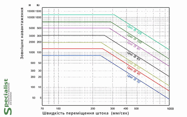
Before attempting to increase the operating speed of pneumatic cylinders, check the chart for the maximum permissible rod speeds:
Several approaches can be used to increase the speed of a pneumatic cylinder:
- Increase air pressure: Increasing the operating pressure in the pneumatic system can raise the cylinder's movement speed. However, the maximum operating pressure recommended for the specific pneumatic cylinder must be observed.
- Use a more powerful compressor: If the compressor supplying compressed air to the pneumatic system has a higher flow capacity, it can increase the air supply and consequently increase the pneumatic cylinder speed.
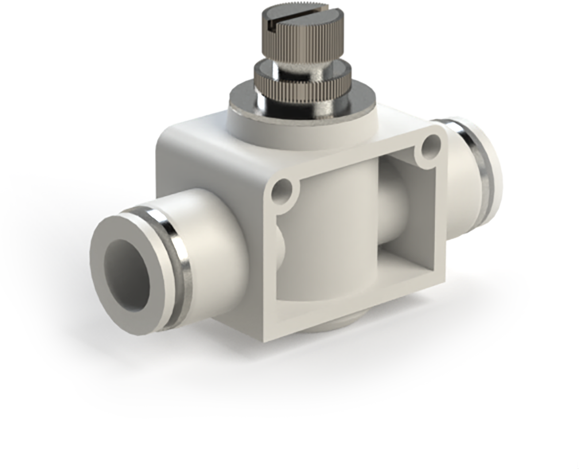
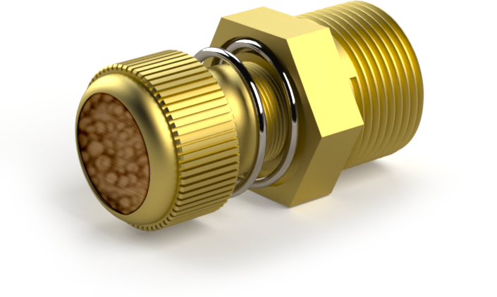
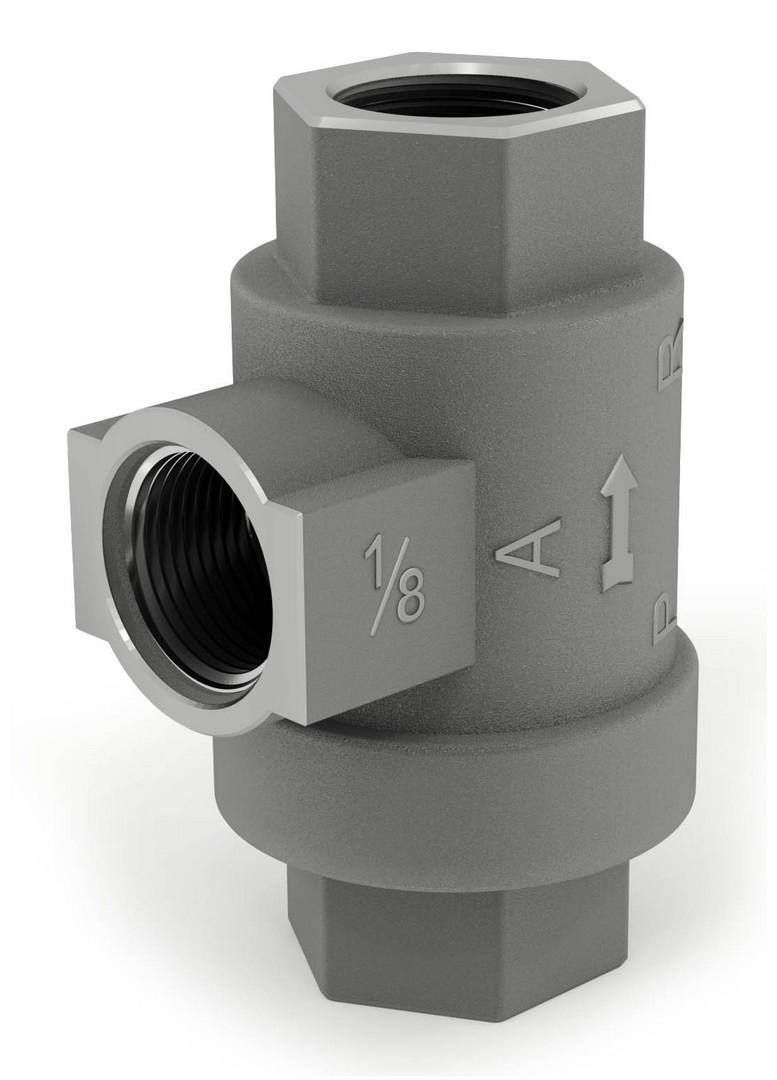
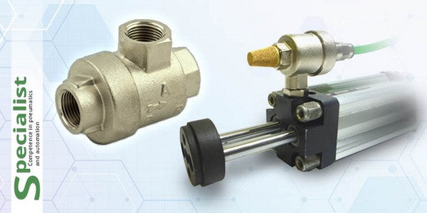
- Use larger air lines: Restricted airflow through narrow air lines can slow down the pneumatic cylinder. Installing larger air lines can improve flow capacity and increase cylinder speed. Additionally, you can use quick exhaust valves for pneumatic cylinders, which help discharge air more rapidly from the chamber opposite the one being filled. This reduces counterforce and increases cylinder operating speed.
- Select a larger pneumatic cylinder: Using a pneumatic cylinder with a larger bore diameter can provide higher movement speed. A larger diameter cylinder can generate greater force and achieve higher speed at a given pressure.
- Minimize load and friction: Ensure the pneumatic cylinder operates with minimal load and friction. Lubrication or the use of low-friction seals can reduce resistance and increase speed.
After determining the required cylinder operating speed, pay attention to rod deceleration at the end of the stroke. As speed increases, the kinetic energy generated by the cylinder also increases.
For high-speed applications, we recommend using cylinders with pneumatic cushioning at the end of the stroke, such as the SC-MS, SC-DNG, SC-DNI, and SC-CPI series.
Pneumatic cushioning
Deceleration of the controlled object occurs during the final portion of the piston travel, which depends on the piston diameter and may range from 10 to 50 mm. The cushioning system is built into the cylinder design and operates automatically. It gradually reduces the cross-sectional area of the air exhaust passage. This reduction creates an air cushion at the end of the stroke, increasing pressure in the exhaust chamber. As a result, the acceleration changes direction, reducing speed and initiating the braking phase of the piston, rod, and connected load.
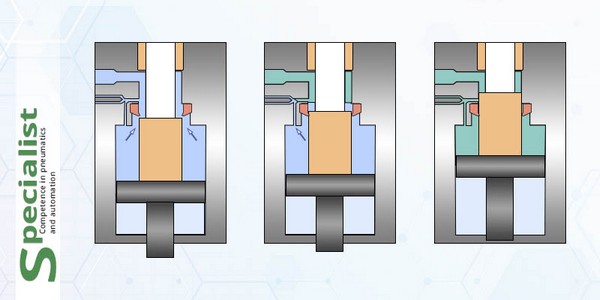
When operating at very high speeds and with a heavy load attached to the pneumatic cylinder rod, pneumatic cushioning may not be sufficient to absorb all the kinetic energy. In such cases, hydraulic shock absorbers should be used.
Hydraulic shock absorber
A hydraulic shock absorber (hydraulic damper) is a device used to control and soften the movement of the piston in a pneumatic cylinder. It is a hydraulic damping component that provides smoother and more controlled deceleration of piston movement at the end positions. They are available in two types.

