







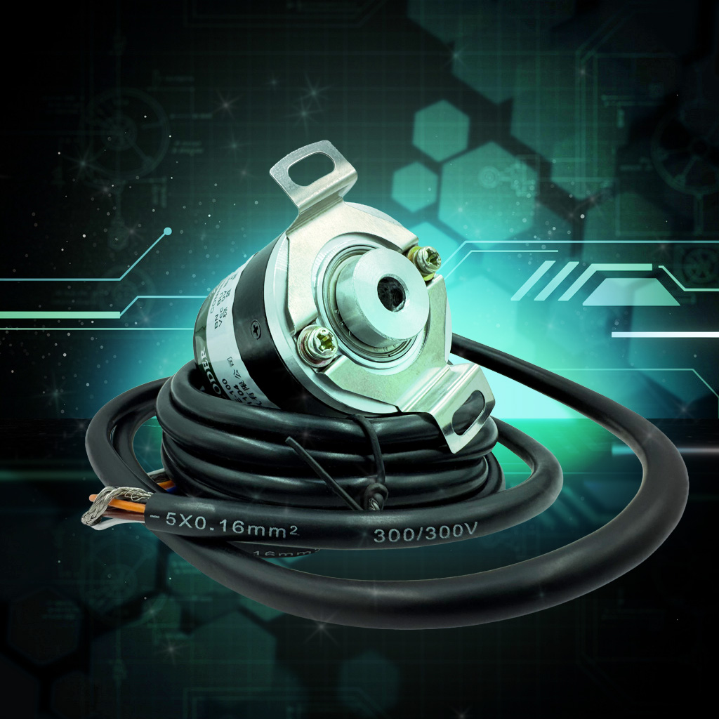
An encoder (position sensor) is an electromechanical device that converts information about mechanical movement or position into electrical signals suitable for processing by electronic control systems. In modern industry and robotics, encoders have become indispensable components that provide precise positioning and motion control in a wide range of applications — from production lines to medical equipment and automotive systems.
With the development of automation and robotics technologies, the requirements for encoder accuracy, reliability, and response speed continue to grow. Modern encoders are capable of providing resolutions of up to millions of pulses per revolution and operating in the most demanding environments. They are key feedback elements that allow control systems to accurately monitor the position, speed, and direction of movement of mechanical components using precise data.
In this article, we will examine the main types of encoders, their operating principles, application features in various control systems, as well as development trends of these essential elements of modern automation.
Main Types of Encoders
Classification by Operating Principle
1. Optical Encoders
Optical encoders are the most common type of position sensor. Their operating principle is based on converting a light beam into electrical signals using an optocoupler (light source and photodetector) and a special coded disc. Selecting the correct sensor model for specific tasks requires professional consultation from our specialists.
Advantages:
- High accuracy and resolution (up to millions of pulses per revolution)
- No mechanical contact between the reading device and the disc
- Wide operating speed range
- Low inertia
Disadvantages:
- Sensitivity to contamination and dust
- Limited performance in extreme operating conditions
2. Magnetic Encoders
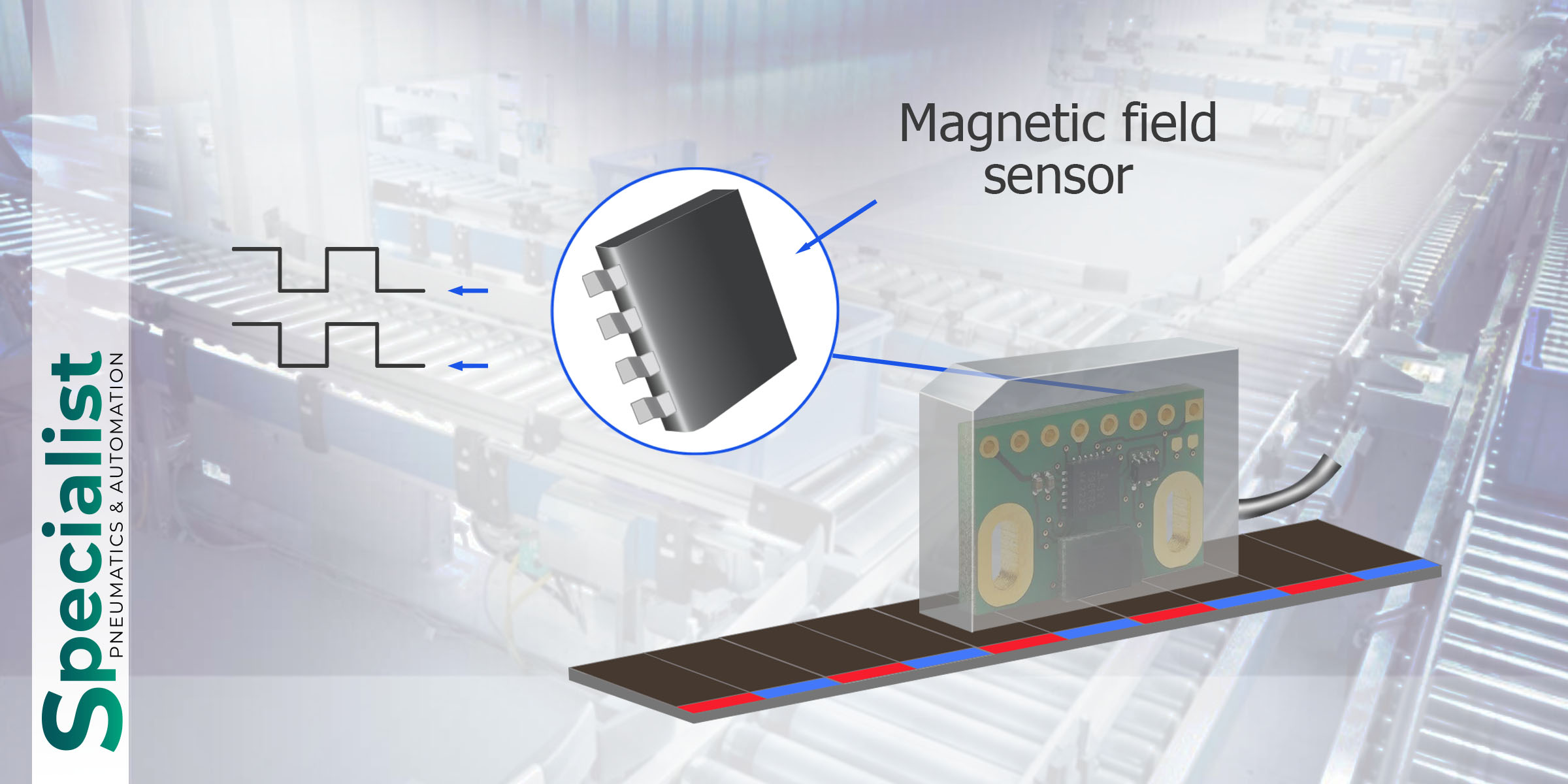
Magnetic encoders use the Hall effect or magnetoresistive effect to determine position. They operate by reading changes in the magnetic field generated by a magnetized disc or strip.
Advantages:
- High accuracy and resolution (up to millions of pulses per revolution)
- No mechanical contact between the reading device and the disc
- Wide operating speed range
- Low inertia
Disadvantages:
- Generally lower accuracy compared to optical encoders
- Sensitivity to external magnetic fields
3. Inductive Encoders
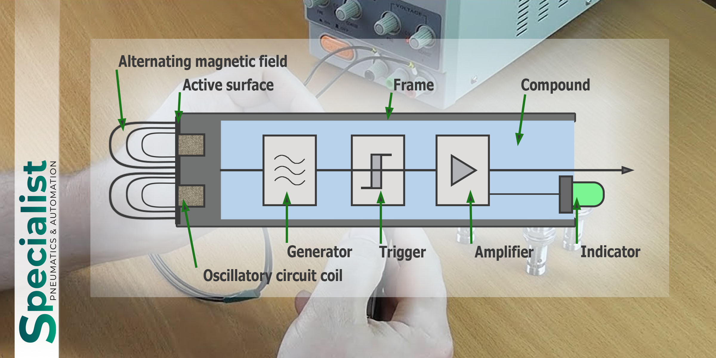
Inductive encoders operate on the principle of inductance change when a metal rotor moves relative to a stator with windings.
Advantages:
- Exceptional reliability and durability
- High resistance to extreme temperatures, vibration, and contamination
- Immunity to electromagnetic interference
Disadvantages:
- Relatively low resolution
- Larger dimensions compared to other types
- Low cost
- Resistance to dust and moisture
- Low power consumption
- Sensitivity to electromagnetic interference
- Resolution limitations
- Rotation speed control
- Distance measurement
- Systems with initial calibration capability
- Binary code
- Gray code (only one bit changes between adjacent positions)
- Serial data transmission formats (SSI, BiSS, EnDat, etc.)
- Systems where loss of position information is unacceptable
- Equipment with frequent power on/off cycles
- Precision positioning systems
- Light source (usually an LED)
- Coded disc with transparent and opaque sections
- Photodetectors (photodiodes or phototransistors)
- Electronic signal processing circuit
- Magnetic disc or strip with alternating poles
- Hall sensors or magnetoresistive elements
- Signal processing circuit
- TTL/CMOS pulses
- Differential signals (line drivers)
- Serial communication protocols (SSI, BiSS, EnDat)
- Industrial interfaces (Profibus, CANopen, EtherCAT)
- High resolution (up to hundreds of thousands of pulses per revolution)
- Minimal errors and long-term stability of characteristics
- Resistance to vibration and cutting fluids
- Compact size and lightweight design (to reduce joint mass)
- High dynamic accuracy
- Absolute position determination after power-up
- Multi-turn functionality
4. Capacitive Encoders
Capacitive encoders operate on the principle of changing electrical capacitance between plates during their relative movement.
Advantages:
Disadvantages:
Classification by Encoder Output Information Type
1. Incremental Encoders
Incremental (relative) encoders generate a sequence of pulses as the shaft rotates. They determine relative displacement, speed, and direction of movement, but not absolute position.
A typical incremental encoder has at least two output channels (A and B) shifted by 90° in phase, allowing the direction of rotation to be determined. A third channel (Z or index) is often added, producing one pulse per full revolution and serving to determine the reference position.
Applications of this sensor:
2. Absolute Encoders
Absolute encoders output a unique code corresponding to a specific angular position of an object at any given moment. They retain position information even when power is turned off.
Absolute encoders can use various encoding methods:
Applications of this sensor:
Classification by Encoder Design
1. Hollow Shaft Encoders
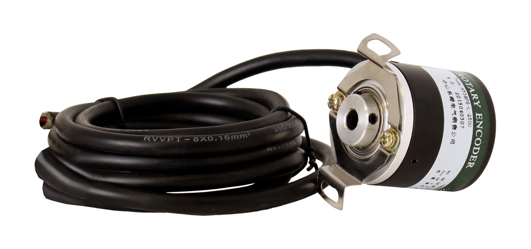
Hollow shaft encoders are mounted directly onto the drive shaft, eliminating the need for couplings and reducing displacement measurement errors.
2. Keyed (Solid Shaft) Encoders
A classic solid-shaft design requiring a coupling for torque transmission and accurate displacement measurement.
3. Modular Encoders
Encoder components (disc and reading head) are mounted separately, allowing integration into limited spaces.
How can encoders be found in our store?
Our company "Specialist" supplies incremental encoders that are used with asynchronous motors. For high-precision positioning tasks, we also recommend servo drives — motors with a built-in encoder that can provide highly accurate positioning, for example, in CNC machines.
Call free of charge within Ukraine
+38 0800 210 317Operating Principle of the Main Types of Encoders
Optical Encoders
The main components of an optical encoder are:
Operating principle of an incremental optical encoder:
1. The LED emits light directed at the coded disc
2. The disc mounted on the shaft contains radial transparent and opaque sectors
3. As the disc rotates, light periodically passes through transparent areas or is blocked by opaque ones
4. Photodetectors convert changes in the light flux into electrical pulses
5. The presence of several tracks with phase shifts allows determination of the direction and speed of rotation
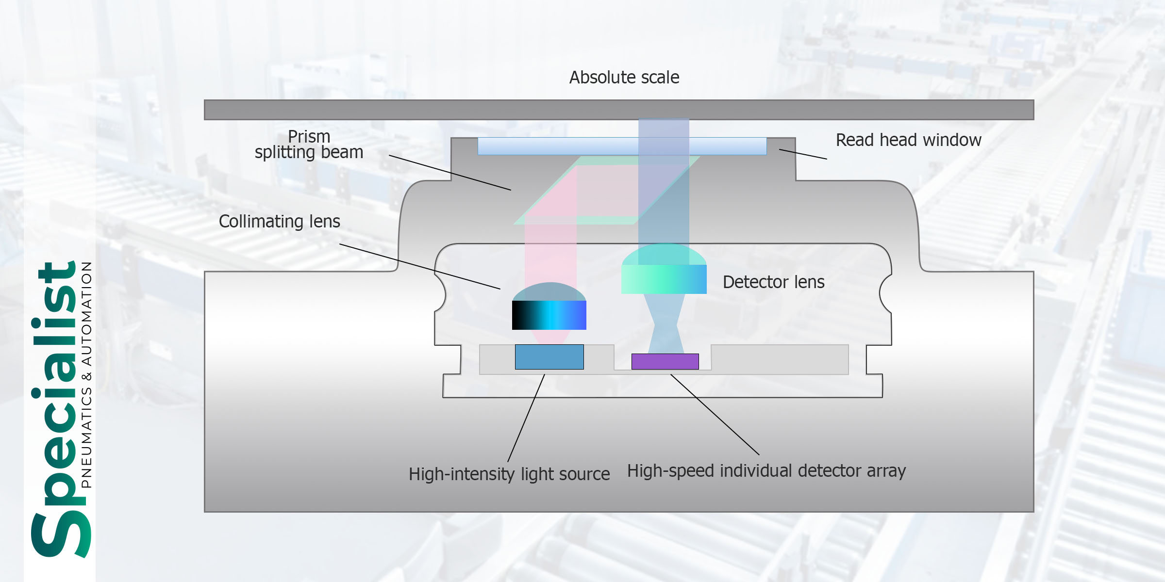
Operating principle of an absolute optical encoder:
In an absolute encoder, the coded disc contains several concentric tracks that form a unique binary code for each angular position. The number of tracks determines the encoder resolution. For example, a 10-bit encoder has 10 tracks and can distinguish 2^10 = 1024 positions per revolution.
Magnetic Encoders
Magnetic encoders use the following components:
Operating principle:
1. A magnetic disc mounted on the shaft creates a changing magnetic field during rotation
2. Hall sensors or magnetoresistive elements respond to changes in the magnetic field
3. The electronic circuit converts these changes into digital signals
Magnetic absolute encoders often use the principle of position encoding with magnetic fields of different spatial frequencies (the Vernier method)
Encoder Characteristics
Main Parameters
1. Resolution - the number of pulses per full shaft revolution (for incremental encoders) or the number of unique codes per revolution (for absolute encoders)2. Accuracy - the maximum error in determining angular position
3. Maximum Rotational Speed - the maximum speed at which the encoder operates correctly
4. Output Interfaces:
5. Operating Temperature Range
6. Protection Class (IP)
7. Mechanical Shaft Load (radial and axial)
8. Rotor Moment of Inertia
Additional Functions
1. Diagnostics - fault detection and transmission of diagnostic information
2. Programmability - the ability to change encoder parameters (resolution, output signal type, etc.)
3. Multi-turn Functionality - counting the number of complete revolutions (for absolute encoders)
4. Electronic Nameplate Function - storing device and calibration information in memory
5. Redundancy - duplication of measurement systems to increase reliability
Applications of Encoders in Control Systems
Industrial Drives and CNC Systems
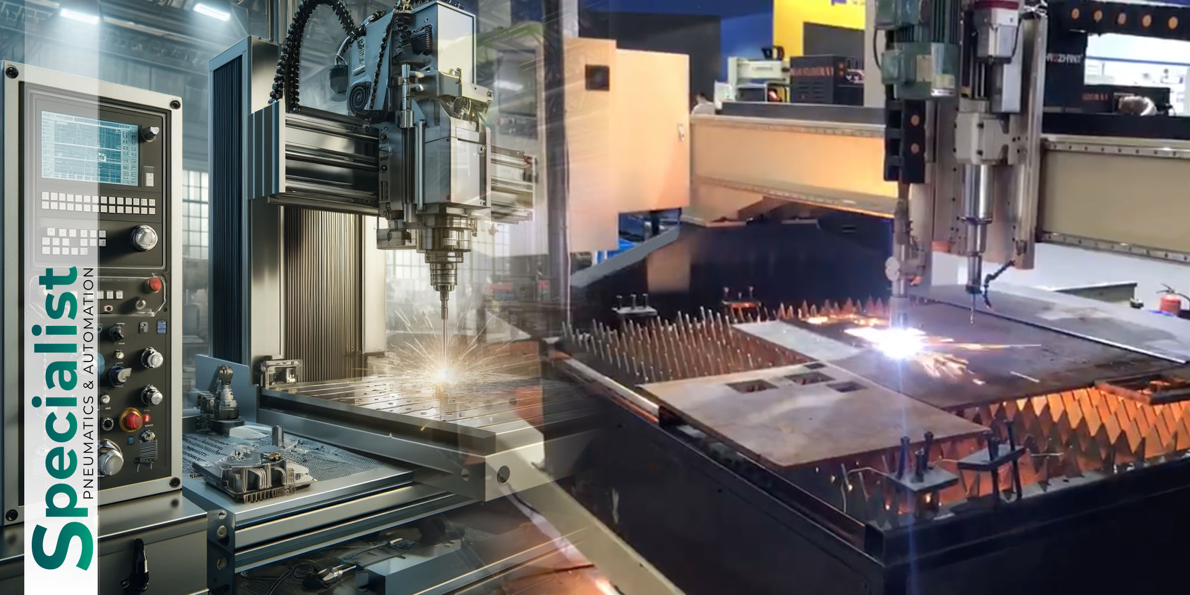
In servo drives and CNC systems, encoders provide precise positioning of machine tool components. They are key elements of the closed-loop control system, allowing accurate monitoring of the position, speed, and acceleration of actuators.
Encoder Requirements for CNC Systems:
Robotics
In robotic systems, encoders are used to track joint positions and ensure precise manipulation. They are especially important in collaborative robots working alongside humans, where high precision and motion safety are required.
Application Features:

Automotive Industry
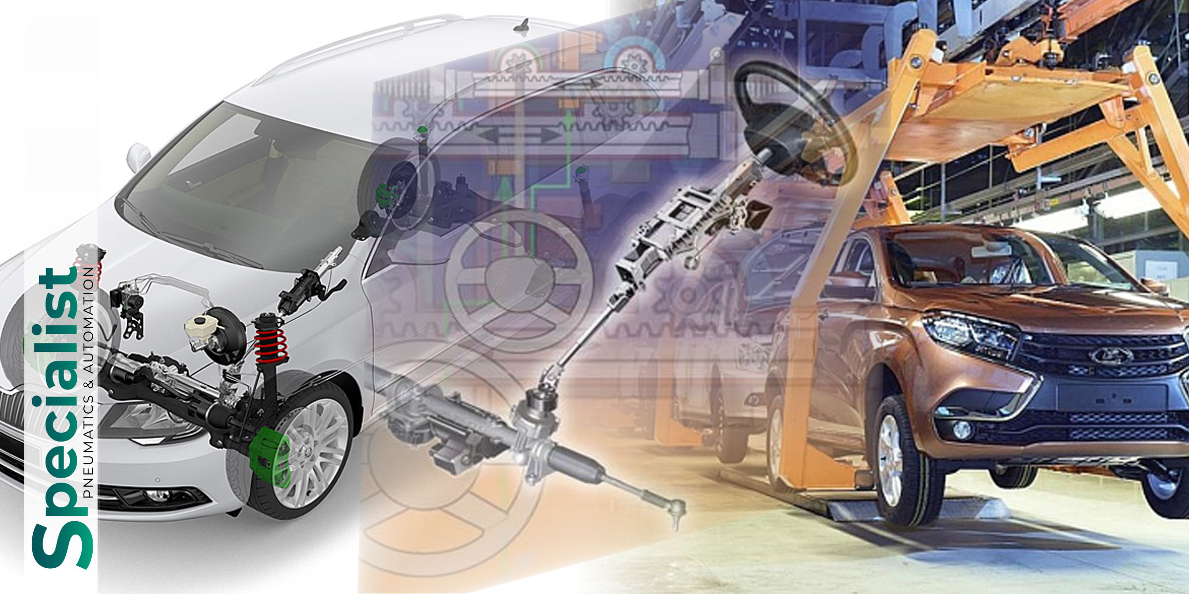
In modern vehicles, encoders are used in various systems:
- Electric power steering
- Dynamic stability control systems
- Electronic accelerator pedal
- Driver assistance and autonomous driving systems
- Power windows and seat adjustment systems
Requirements:
- Enhanced reliability and durability
- Operation across a wide temperature range
- Resistance to vibration, moisture, and aggressive environments
- Low cost in mass production
Medical Equipment
In medical devices, encoders are used for high-precision positioning in:
- Surgical robots
- Tomographs and X-ray machines
- Radiation therapy equipment
- Automated bio-sample analysis systems
Requirements:
- Exceptional reliability and accuracy
- Sterilizability or suitability for operation in clean rooms
- Silent operation
- Electromagnetic compatibility with other equipment

Renewable Energy
In wind turbines and solar tracking systems, encoders ensure the optimal positioning of equipment relative to the energy source:
- Positioning of wind turbine blades
- Orientation of solar panels
- Control of generator rotational speed
Requirements:
- Extreme resistance to weather conditions
- Long service life without maintenance
- Ability to operate under high levels of electromagnetic interference
.jpg)
Integration of Encoders into Control Systems
Electrical Interfaces
1. Analog Interfaces
- Sinusoidal signal (1Vpp)
- Current loop signal (4-20 mA)
2. Digital Interfaces
- Differential line connection (RS-422)
- TTL-compatible signals
- Serial interfaces (SSI, BiSS, EnDat)
- Industrial networks (Profibus, CANopen, EtherCAT, PROFINET)
Software Aspects
For proper operation with encoders in control systems and accurate position determination, it is necessary to implement:
- Quadrature signal decoding
- Pulse counting and direction detection
- Index signal processing
- Compensation of mechanical errors
- Signal filtering to eliminate noise and chatter
Problems and Solutions
1. Electromagnetic Interference
- Use of shielded cables
- Differential signal transmission
- Power supply and signal line filtering
2. Mechanical Problems
- Use of flexible couplings to compensate for misalignment
- Use of precision bearings
- Balancing of rotating components
3. Environmental Conditions
- Sealed housings with a high protection rating
- Special materials for operation in aggressive environments
- Temperature compensation for stable operation across a wide temperature range, ensuring proper operation sequences
Modern Trends in Encoder Development
Miniaturization
Modern technologies make it possible to create increasingly compact encoders without compromising performance. Encoders with diameters of less than 10 mm have been developed for use in medical devices and miniature robots.
Integration of Additional Functions
Many modern encoders include additional sensors:
- Temperature sensors for monitoring operating conditions
- Accelerometers for vibration detection
- Gyroscopes for comprehensive position determination
Intelligent Encoders
Built-in microcontrollers make it possible to implement:
- Self-diagnostics and predictive maintenance
- Adaptive signal filtering
- Compensation of systematic errors
- Protection against unauthorized access

